
Audio. - Here is Circuit Schematic Audio Signal Source using IC L8038. The circuit shown like in figure 1 below, can be roughly divided into three parts: the oscillator based around the ICL8038 chip, the selection logic based on the CD4017 and CD4066 and the offset generation and output buffers, based on the LF412. Apologies for the cramped schematic, I had to keep the image size small, and the width under 640 pixels!
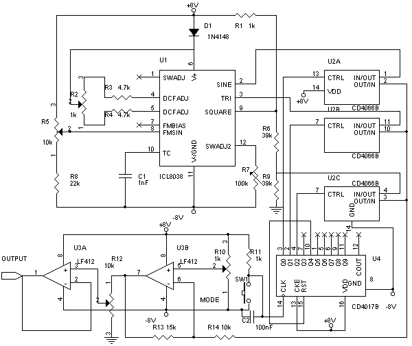 |
| Figure 1. Schematic Audio Signal Source using IC L8038 (Source: www.wiredworld.tripod.com/) |
The oscillator is a standard 8038-based oscillator circuit, taken from the ICL8038 datasheet. The timing resistor chosen is rather small, to give a wide range of frequencies. This range might be a little too large, making precise frequency setting difficult. In that case, the freqency range may be split into two parts, using two capacitors which can be switched using an SPDT switch. Note that the 8038 is powered from a split supply, not a single supply, to generate a symmetrical waveform without the need for capacitor coupling. Two sine wave adjustment terminals (Pins 1 and 12) are provided, however only one is used. This gives a sinewave distortion of about 1%. To achieve better distortion figures, the circuit shown in Figure 4 of the ICL8038 datasheet may be used. The 8038 is powered from slightly less than +8V to allow the tuning voltage to go above the supply rail. This allows for maximum sweep range (1000:1), however the output waveform tends to be slightly asymmetric because of this. This may be compensated using the offset control R10. R2 controls the duty cycle of the oscillator. R7 acts as the sinewave distortion adjustment. The square wave output of the 8038 is an open-collector output. Hence, a 1k pullup resistor is provided. The sine and triangle outputs are about 5Vpp, while the square wave is 16Vpp. Hence to equalize the different outputs, the square wave is attenuated using a fixed attenuator formed by R6 and R9. A 47k pot may be substituted to make the attenuation level adjustable.
Thank you for your coming here in Electronic Index blog, we hope the article above will help you to know more about your an electronic circuit schematic design and simulation and other. Please comment here when you want to share and other. Thank you.
0 comments:
Post a Comment