
PowerSupply. - Here is Circuit schematic Negative Voltage Power Supply using IC LM555. As we know that A negative supply can be generated by a “Charge-Pump” circuit created with a 555, diodes and capacitors.
Another advantage of this circuit is that, the negative voltage together with the original positive supply can be used to simulate a dual supply. This circuit diagram like in figure 1 below shows how to obtain a negative voltage from a positive voltage supply.
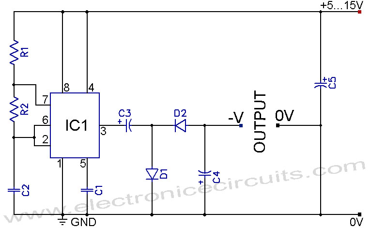 |
| Figure 1. Circuit schematic Negative Voltage Power Supply using IC LM555 (Source: www.electronicecircuits.com) |
Component List
- C1 0.1µF (104)
- C2 0.022µF (223)
- C3 22µF 25V
- C4 33µF 25V
- C5 100µF 25V
- R1 4.7kΩ
- R2 33kΩ
- D1 1N4002
- D2 1N4002
- IC1 NE555
The Original Article : "555 Negative Voltage Power Supply"
Thank you for your coming here in Electronic Index blog, we hope the article above will help you to know more about your an electronic circuit schematic design and simulation and other. Please comment here when you want to share and other. Thank you.
0 comments:
Post a Comment