
PowerSupply. - Here is Circuit Schematic Power Supply Failure Indicator using IC LM741. Many circuits, especially digital systems such as random access memories and digital clocks, must have a continuous power supply to ensure correct operation. If the supply to a RAM is interrupted then the stored information is lost, as is the time in the case of a digital clock.
The supply failure indicator described here will sense the interruption of the power supply and will light a LED when the supply is restored, thus informing the microprocessor user that the information stored in RAM is garbage and must be re-entered, and telling the digital clock owner that his clock must be reset to the correct time.
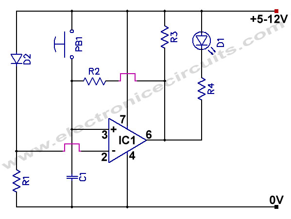 |
| Figure 1. Schematic Power Supply Failure Indicator using IC LM741 (Source: www.electronicecircuits.com) |
When the supply is initially switched on the inverting input of IC1 is held at 0.6V below positive supply by D2. Pressing the reset button takes the non-inverting input of IC1 to positive supply potential, so the output of IC1 swings high, holding the non-inverting input high even when the reset button is released. LED D1 is therefore not lit.
Component List
- R1 100kΩ
- R2 10kΩ
- R3 10kΩ
- R4 680Ω
- C1 10nF (103)
- D1 LED
- D2 1N4148
- IC1 741
- PB1 Push Button Switch
Thank you for your coming here in Electronic Index blog, we hope the article above will help you to know more about your an electronic circuit schematic design and simulation and other. Please comment here when you want to share and other. Thank you.
0 comments:
Post a Comment